In precision manufacturing—from automotive component production to aerospace part fabrication—burrs (small, jagged material protrusions formed during machining, cutting, or stamping) pose critical risks: they compromise part fit, damage mating components, and create safety hazards for operators. Deburring machines automate the removal of these burrs while often integrating edge rounding (creating controlled, smooth radii on part edges) to meet functional and regulatory standards (e.g., ISO 13715 for edge quality). This guide explains the technical principles of deburring machines, their core operating mechanisms, types, and how they deliver consistent, repeatable results for diverse manufacturing applications.
1. Foundational Context: What Are Burrs, and Why Do They Matter?
Before diving into machine mechanics, it is critical to understand the problem deburring machines solve. Burrs form when machining processes (e.g., laser cutting, milling, drilling) exceed a material’s yield strength, causing plastic deformation at the cut edge. There are three primary burr types, each requiring targeted removal strategies:
- Poisson Burrs: Formed when material is compressed (e.g., punching sheet metal), pushing material outward at the cut edge.
- Tear Burrs: Occur when brittle materials (e.g., cast iron) or thin gauges (e.g., 0.5 mm aluminum) are cut, leaving ragged, torn edges.
- Roll Burrs: Result from high-speed cutting (e.g., CNC milling), rolling material into a curled protrusion along the edge.
Unaddressed burrs lead to:
- Assembly Failures: Burrs prevent precise part mating (e.g., a burred bolt hole may not align with a nut, causing thread damage).
- Safety Risks: Sharp edges cause lacerations to operators during handling (a major OSHA recordable incident risk).
- Performance Degradation: In dynamic applications (e.g., engine valves), burrs can chip off and contaminate lubricants, leading to premature wear.
Deburring machines resolve these issues by removing burrs and, in many cases, rounding edges to a specified radius (typically 0.1–2 mm, per application requirements).
All deburring machines follow a universal workflow: targeted material removal (without damaging the part’s base geometry) using mechanical, abrasive, or chemical forces. The key distinction lies in how force is applied—tailored to material type (e.g., aluminum vs. stainless steel), burr size (0.01–1 mm), and part complexity (simple flat sheets vs. intricate 3D components).
The standard operational sequence is:
1. Part Loading: Manual (for low-volume, complex parts) or automated (conveyor belts, robotic arms for high-volume production) placement of parts into the machine.
2. Burr Detection (Optional): Advanced CNC models use vision systems or laser scanners to map burr locations—critical for intricate parts (e.g., aerospace turbine blades) where burrs may be hidden in recesses.
3. Material Removal: Application of controlled force via tools (abrasives, brushes, media) to remove burrs. Edge rounding occurs simultaneously if the tool path or media is adjusted to create a radius.
4. Part Cleaning: Removal of debris (abrasive dust, metal shavings) via compressed air, vacuum systems, or ultrasonic cleaning (for precision parts).
5. Quality Inspection: Post-process checks (vision systems, tactile probes) to verify burr removal and edge radius compliance (e.g., ensuring a 0.5 mm radius on a medical device component).
3. Types of Deburring Machines: Mechanisms & Ideal Applications
Deburring machines are categorized by their material removal method, each optimized for specific part geometries, volumes, and materials. Below is a technical breakdown of the most common types:
| Machine Type | Core Mechanism | Key Technical Specs | Ideal Applications |
|----------------------------|--------------------------------------------------------------------------------|-------------------------------------------------------------------------------------|-------------------------------------------------------------------------------------|
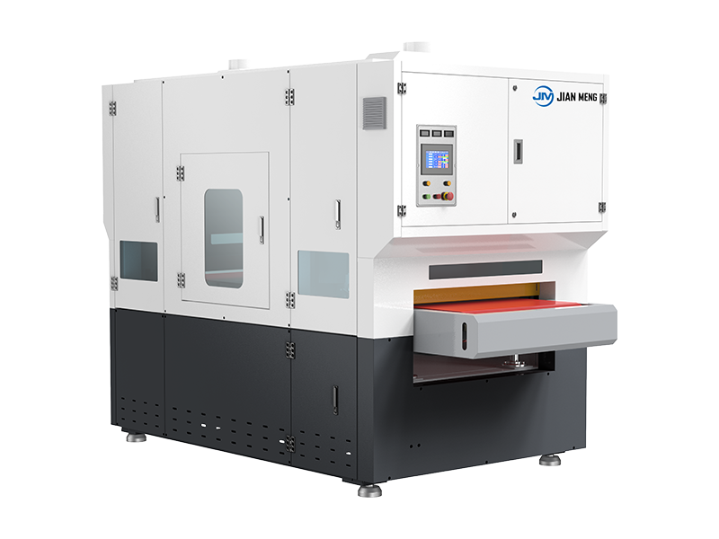
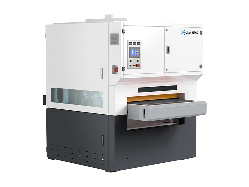
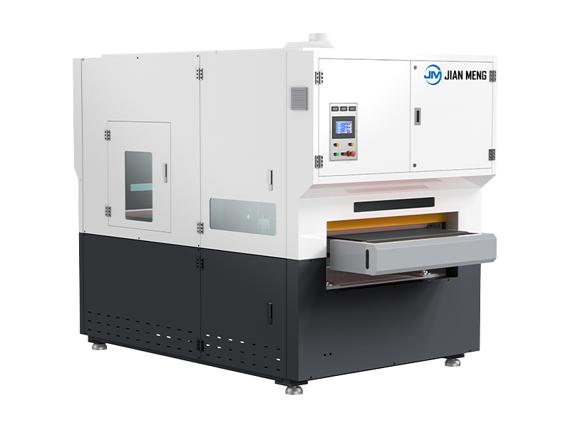
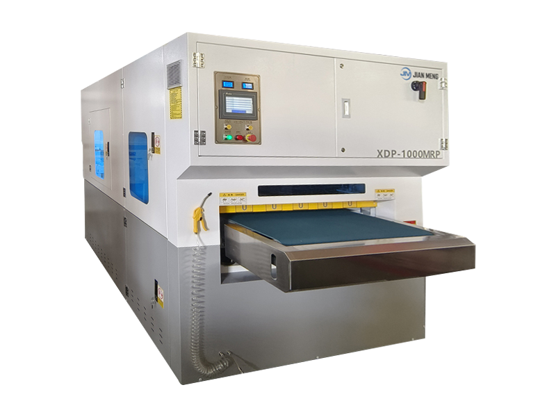
| Abrasive Belt/Disc Deburrers | Rotating abrasive belts (60–320 grit) or discs (aluminum oxide, silicon carbide) that grind burrs via contact with part edges. | - Belt speed: 5–20 m/s<br>- Grit range: 60 (aggressive)–320 (fine)<br>- Part size capacity: 10 mm–2 m (length) | Flat/simple parts (e.g., laser-cut sheet metal, aluminum brackets), high-volume production (1,000+ parts/hour). |
| Rotary Brush Deburrers | Nylon, steel, or brass brushes (tufted or twisted) that conform to part contours, removing burrs without scratching delicate surfaces. | - Brush speed: 500–3,000 RPM<br>- Brush material: Nylon (soft, for plastics/aluminum); steel (hard, for stainless steel)<br>- CNC programmability (optional) | Complex 3D parts (e.g., automotive engine blocks, aerospace fasteners), parts with recesses or holes. |
| Vibratory Finishing Machines | Parts are tumbled in a vibrating chamber filled with abrasive media (ceramic, plastic, or steel pellets) and a cleaning compound. Media impacts burrs to remove them. | - Vibration frequency: 1,000–3,600 Hz<br>- Media size: 1–20 mm (matched to part size)<br>- Cycle time: 15 min–4 hours | Small, high-volume parts (e.g., screws, washers, jewelry components), parts with hard-to-reach internal burrs (e.g., drilled holes). |
| CNC Deburring Centers | Robotic arms or multi-axis spindles equipped with custom tools (brushes, abrasive bits) programmed to follow precise tool paths (CAD/CAM-derived). | - Axis count: 3–6 axes (for 3D parts)<br>- Positioning accuracy: ±0.01 mm<br>- Integration with vision systems (for burr mapping) | High-precision, low-to-medium volume parts (e.g., aerospace turbine blades, medical implants), parts requiring complex edge rounding. |
| Electrochemical Deburring (ECD) | Uses an electrolyte solution and electrical current to dissolve burrs (anodic dissolution)—no mechanical contact with the part. | - Current density: 10–100 A/dm²<br>- Electrolyte type: Sodium nitrate (for steel); citric acid (for aluminum)<br>- Deburring precision: ±0.005 mm | Micro-burrs on delicate parts (e.g., electronic connectors, fuel injector nozzles), parts where mechanical force would cause damage. |
4. Edge Rounding: Technical Integration with Deburring
Edge rounding is not just a cosmetic step—it enhances part durability (reduces stress concentrations) and compliance with industry standards (e.g., FDA requirements for medical devices, which mandate rounded edges to prevent tissue damage). Deburring machines achieve edge rounding by modifying their material removal method:
- Abrasive Machines: Adjust belt/disc angle (typically 15–45° relative to the part edge) and pressure to grind a radius instead of a sharp edge. For example, a 30° angle on a 120-grit belt creates a 0.3 mm radius on 2 mm thick steel.
- Rotary Brushes: Use tapered or contoured brush heads that contact the edge at multiple points, gradually wearing down the corner into a radius. Nylon brushes are preferred for soft metals (aluminum) to avoid over-removal.
- Vibratory Machines: Select media with rounded shapes (e.g., ceramic cylinders) that tumble against the edge, creating a uniform radius without sharp corners. Cycle time is extended by 20–50% to achieve the desired radius.
- CNC Centers: Program tool paths to trace a circular arc along the edge (e.g., a 0.5 mm radius arc for a medical instrument), ensuring consistency across every part.
*Critical Parameter*: Edge radius tolerance is typically ±0.1 mm for industrial parts and ±0.05 mm for aerospace/medical components—deburring machines with closed-loop feedback (vision systems) maintain this precision.
5. Key Advantages of Automated Deburring Machines Over Manual Methods
Manual deburring (using files, sandpaper, or hand brushes) is error-prone, labor-intensive, and inconsistent. Automated machines address these limitations:
1. Consistency: CNC and robotic deburrers deliver identical results across 100–100,000+ parts—critical for mass production (e.g., automotive door hinges).
2. Precision: ECD and CNC machines remove micro-burrs (0.01 mm) that are invisible to the naked eye, meeting aerospace AS9100 or medical ISO 13485 standards.
3. Efficiency: A single automated machine replaces 3–5 manual operators, reducing cycle time from minutes per part to seconds (e.g., 5 seconds/part for sheet metal vs. 2 minutes manually).
4. Material Preservation: Controlled force prevents over-deburring (which can reduce part thickness or damage features like threads)—unlike manual filing, which often removes excess material.
6. Selection Criteria for Deburring Machines
To choose the right machine, align its capabilities with your project’s technical requirements:
6.1 Material & Burr Characteristics
- Material Hardness: Soft metals (aluminum, brass) require nylon brushes or fine-grit abrasives; hard metals (stainless steel, titanium) need steel brushes or aggressive abrasives (60-grit aluminum oxide).
- Burr Size/Location: Surface burrs (0.1–1 mm) work with abrasive belts; internal burrs (e.g., in drilled holes) need vibratory finishing or ECD.
6.2 Part Complexity & Volume
- Simple/Flat Parts (High Volume): Abrasive belt deburrers (fast, low cost).
- Complex 3D Parts (Low Volume): CNC deburring centers (programmable, precise).
- Small Parts (Very High Volume): Vibratory finishing machines (batch processing, low labor).
6.3 Quality Requirements
- Industrial Grade (±0.1 mm radius): Standard abrasive or brush machines.
- Precision Grade (±0.05 mm radius): CNC centers with vision systems or ECD machines.