A vertical V groover machine (also known as vertical V-cutting machine or vertical V-grooving equipment) is a specialized precision processing machine widely used in metalworking, sheet metal fabrication, and composite material processing industries. It is designed to cut precise V-shaped grooves, bevels, or chamfers on the surface or edge of workpieces, with a vertical structural design that ensures stability, accuracy, and efficiency during processing. Unlike horizontal V groover machines, vertical models offer better space utilization, easier workpiece loading and unloading, and superior adaptability to small-to-medium-sized workpieces and complex processing scenarios. This article systematically elaborates on the definition, core working principles, main types, typical application scenarios, process optimization, and maintenance guidelines of vertical V groover machines, integrating practical technical parameters and industry operational experience to provide comprehensive guidance for engineers, production managers, quality control personnel, and maintenance technicians.
I. Overview and Core Definition of Vertical V Groover Machines
In sheet metal fabrication, metal processing, and related industries, V-shaped grooves are essential for workpiece assembly, bending, welding, and
aesthetic finishing.
V grooves not only enhance the structural stability of assembled components but also ensure precise bending angles, reduce welding gaps, and improve the overall appearance of products. For example, in the production of metal cabinets, decorative panels, and automotive parts, precise V grooves are required to achieve seamless assembly and neat appearance. A vertical V groover machine specializes in creating these V-shaped grooves with high precision, consistent dimensions, and smooth surfaces, addressing the limitations of manual grooving (low efficiency, poor accuracy) and horizontal machines (large space occupation, inconvenient operation for small workpieces).
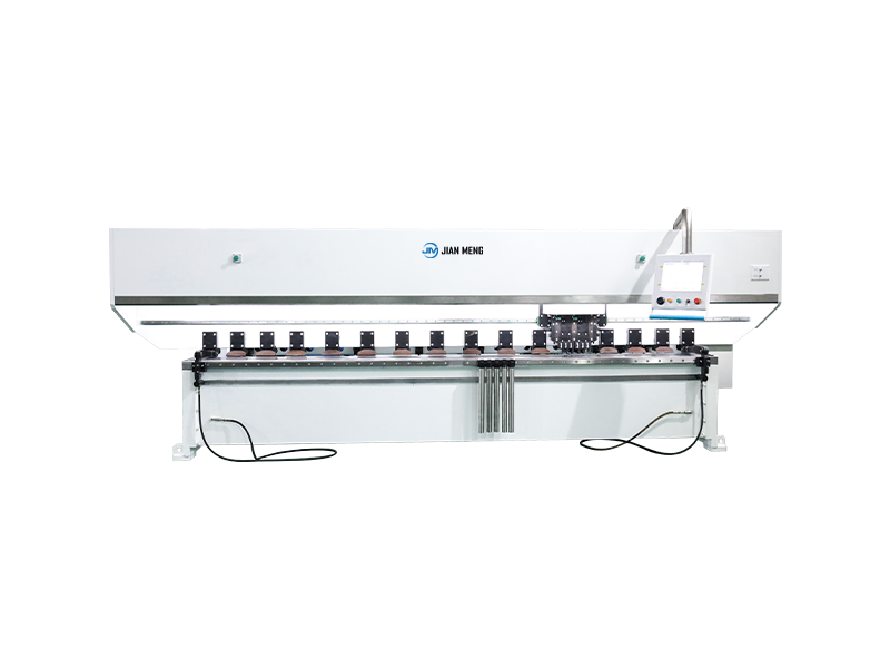
The core feature of a vertical V groover machine is its vertical configuration, where the cutting tool is mounted vertically above the workpiece table, and the workpiece is placed horizontally on the table for processing. This design allows for easy access to the workpiece, simplifies loading and unloading operations, and ensures that the cutting force acts vertically downward, reducing workpiece deformation and improving processing stability. Vertical V groover machines are capable of processing a wide range of materials, including various metals (steel, stainless steel, aluminum, copper, and their alloys), composite materials, and some non-metallic materials (such as PVC and acrylic), making them versatile in multiple manufacturing fields.
The key performance indicators of vertical V groover machines include groove angle accuracy (usually ±0.1°), groove depth precision (±0.05mm), processing speed, and tool life. Advanced models are equipped with numerical control (CNC) systems to achieve automatic parameter adjustment, continuous processing, and high repeatability, meeting the high-precision requirements of modern manufacturing.
II. Core Working Principle of Vertical V Groover Machines
The operation of a vertical V groover machine is based on the principle of precision mechanical cutting, where a rotating V-shaped cutting tool (or multiple tools) is used to remove material from the workpiece surface to form a V-shaped groove. The working process can be divided into five key stages, ensuring efficient and precise grooving:
1. Workpiece Fixing
The workpiece is placed horizontally on the machine’s worktable, which is equipped with a clamping system (such as hydraulic clamps, pneumatic clamps, or manual clamps) to fix the workpiece firmly. The clamping force is adjustable according to the workpiece material and thickness to avoid movement or deformation during processing. For thin or delicate workpieces, soft clamping pads are used to prevent surface scratches or damage.
2. Tool Installation and Adjustment
The vertical V groover machine uses a V-shaped cutting tool, which is mounted on the vertical spindle. The tool is usually made of high-speed steel (HSS), carbide, or diamond, depending on the workpiece material and processing requirements. Before processing, the tool is adjusted to the required groove angle (common angles include 30°, 45°, 60°, and 90°) and depth by adjusting the spindle height and tool position. The tool’s rotation speed is also set according to the material hardness and groove size to ensure smooth cutting and long tool life.
3. Cutting Process Initiation
When the machine is started, the vertical spindle drives the V-shaped tool to rotate at a high speed (usually 1000–5000 rpm). The worktable (or the spindle) moves linearly along the predetermined path, allowing the rotating tool to contact the workpiece surface and remove material. The cutting direction can be adjusted according to the groove position, and the feed rate (usually 5–50 mm/min) is controlled to ensure uniform material removal and smooth groove surfaces.
4. Groove Forming
As the tool moves along the workpiece, the V-shaped cutting edge removes material to form a precise V-shaped groove. The groove angle is determined by the tool’s V-angle, and the groove depth is controlled by the spindle’s vertical position. For deep grooves, multiple passes may be required, with each pass removing a small amount of material to avoid tool damage and workpiece deformation. During processing, a cutting fluid is usually used to cool the tool and workpiece, reduce friction, and flush away cutting chips, ensuring processing quality and extending tool life.
5. Processing Completion and Unloading
After the groove is formed, the machine stops automatically, and the clamping system releases the workpiece. The operator checks the groove dimensions and surface quality (using tools such as angle gauges, depth gauges, and surface roughness testers) to ensure they meet the requirements. The workpiece is then unloaded, and the worktable is cleaned to prepare for the next processing cycle.
III. Main Types of Vertical V Groover Machines and Their Working Principles
Vertical V groover machines are classified into various types based on their control mode, tool configuration, processing capacity, and application scenarios. Each type has unique characteristics, working principles, and applicable fields. The following is a systematic classification and detailed introduction of mainstream vertical V groover machines:
1. Based on Control Mode
1.1 Manual Vertical V Groover Machine
This type of machine is operated manually, with the operator adjusting the tool position, groove depth, and feed rate manually. It is simple in structure, low in cost, and suitable for small-batch, low-precision processing scenarios, such as small workshops and prototype production.
Working Principle: The workpiece is clamped manually on the worktable, and the operator adjusts the vertical spindle height to set the groove depth. The V-shaped tool is driven by a motor to rotate, and the operator pushes the worktable (or the spindle) along the cutting path to complete the grooving. The groove angle is fixed by the tool’s V-angle, and the feed rate is controlled by the operator’s manual operation.
Key Advantages: Simple structure, easy operation, low equipment cost, small space occupation, suitable for small-batch and prototype processing. Limitations: Low processing precision, low efficiency, high labor intensity, not suitable for mass production or high-precision requirements. Best For: Small workshops, prototype production, and low-precision sheet metal processing, such as simple decorative panels and small metal parts.
1.2 Semi-Automatic Vertical V Groover Machine
This type of machine integrates manual and automatic functions, with automatic tool rotation and feed rate control, while the workpiece loading, unloading, and tool adjustment are completed manually. It balances processing efficiency and cost, suitable for medium-batch, medium-precision processing scenarios.
Working Principle: The machine is equipped with a speed-adjustable motor and a feed mechanism, which can automatically control the tool rotation speed and feed rate. The operator clamps the workpiece, adjusts the tool position and groove parameters (depth, angle), and starts the machine. The feed mechanism drives the worktable or spindle to move linearly, completing the grooving process automatically. After processing, the operator unloads the workpiece and loads a new one.
Key Advantages: Higher processing efficiency and precision than manual models, lower labor intensity, moderate cost, easy to operate. Limitations: Still requires manual loading and unloading, not suitable for large-scale mass production. Best For: Medium-batch sheet metal processing, such as metal cabinets, door panels, and automotive decorative parts.
1.3 CNC Vertical V Groover Machine
This is the most advanced type of vertical V groover machine, equipped with a numerical control system (such as CNC system or PLC control) to realize automatic parameter setting, workpiece positioning, cutting, and quality inspection. It is suitable for high-precision, large-batch, and complex processing scenarios, widely used in high-end manufacturing fields.
Working Principle: The operator inputs the processing parameters (groove angle, depth, length, feed rate, tool speed) into the CNC system, which automatically controls the spindle rotation, worktable movement, and tool adjustment. The workpiece is clamped by an automatic clamping system, and the machine completes the grooving process automatically according to the preset program. Advanced models can integrate automatic loading and unloading systems (such as robotic arms) to realize fully automated production. Some CNC models also support multi-tool processing, allowing for simultaneous grooving of multiple positions or different angles.
Key Advantages: High processing precision (groove angle accuracy ±0.05°, depth precision ±0.02mm), high efficiency, good repeatability, suitable for complex and large-batch processing, easy integration into automated production lines. Limitations: High initial investment and maintenance costs, requiring professional operators. Best For: High-precision sheet metal processing, aerospace parts, automotive precision components, and large-batch production of decorative panels.
2. Based on Tool Configuration
2.1 Single-Tool Vertical V Groover Machine
This type of machine is equipped with a single vertical spindle and a single V-shaped cutting tool, suitable for processing single-angle, single-depth V grooves. It is simple in structure, easy to maintain, and suitable for basic grooving requirements.
Working Principle: The single V-shaped tool is mounted on the vertical spindle, and the machine processes the workpiece by moving the worktable or spindle along the cutting path. The groove angle is fixed by the tool’s V-angle, and the depth is adjusted by the spindle height. It is suitable for processing simple V grooves with fixed angles, such as 45° or 90° grooves.
Key Advantages: Simple structure, easy maintenance, low cost, suitable for basic grooving needs. Limitations: Only suitable for single-angle processing, low efficiency for complex grooves.Best For: Basic sheet metal processing, such as simple bending preparation and decorative grooving.
2.2 Multi-Tool Vertical V Groover Machine
This type of machine is equipped with multiple vertical spindles and different types of V-shaped tools, allowing for simultaneous processing of multiple grooves, different angles, or different depths. It is suitable for complex processing requirements and large-batch production.
Working Principle: Multiple tools are mounted on separate vertical spindles, each set to the required groove angle and depth. The worktable moves linearly, and the multiple tools process the workpiece simultaneously, completing multiple grooving operations in one pass. The tools can be adjusted independently to meet different processing requirements, such as processing V grooves of different angles on the same workpiece.
Key Advantages: High processing efficiency, suitable for complex and multi-groove processing, reducing processing time and labor costs. Limitations: Complex structure, high maintenance requirements, higher cost. Best For: Large-batch production of complex sheet metal parts, such as automotive body parts, aerospace components, and multi-groove decorative panels.
3. Based on Processing Capacity
3.1 Small-Sized Vertical V Groover Machine
This type of machine has a small worktable size (usually 500mm × 300mm or smaller) and is suitable for processing small workpieces, such as small metal panels, electronic component shells, and precision hardware.
Key Advantages: Compact structure, small space occupation, easy to move and install, suitable for small workshops and laboratories. Limitations: Limited processing size, not suitable for large workpieces. Best For: Small workpieces, precision hardware, and laboratory prototype processing.
3.2 Medium-Sized Vertical V Groover Machine
This is the most common type of vertical V groover machine, with a worktable size of 1000mm × 500mm to 2000mm × 1000mm, suitable for processing medium-sized workpieces, such as metal cabinets, door panels, and automotive decorative parts.
Key Advantages: Balanced processing capacity and space occupation, suitable for most sheet metal processing scenarios, moderate cost. Best For: Medium-sized sheet metal parts, batch production of decorative panels, and general manufacturing.
3.3 Large-Sized Vertical V Groover Machine
This type of machine has a large worktable size (more than 2000mm × 1000mm) and is suitable for processing large workpieces, such as large metal plates, ship components, and building decorative panels.
Key Advantages: Large processing capacity, suitable for large workpieces, high stability. Limitations: Large space occupation, high cost, complex installation. Best For: Large-scale sheet metal processing, building decoration, and shipbuilding industry.
IV. Typical Application Scenarios of Vertical V Groover Machines
Vertical V groover machines are widely used in various manufacturing industries, especially in fields requiring precise V grooves for assembly, bending, or aesthetic purposes. The following are typical application scenarios and corresponding machine types:
1. Sheet Metal Fabrication Industry
The sheet metal fabrication industry is the primary application field of vertical V groover machines. Sheet metal parts (such as metal cabinets, enclosures, door panels, and shelves) require precise V grooves to facilitate bending and assembly. Vertical V groover machines can process uniform V grooves on sheet metal surfaces, ensuring accurate bending angles and seamless assembly.
For example, in the production of metal cabinets, vertical V groover machines are used to process V grooves on the edges of sheet metal plates, allowing the plates to be bent into a box shape with tight seams. CNC vertical V groover machines are widely used in large-batch sheet metal production, ensuring consistent groove dimensions and high processing efficiency.
2. Automotive Industry
The automotive industry requires a large number of precision sheet metal components (such as body panels, door frames, dashboard brackets, and decorative parts) with precise V grooves for assembly and aesthetics. Vertical V groover machines, especially CNC and multi-tool models, are used to process these components, ensuring high precision and consistency.
For example, automotive body panels often require V grooves to facilitate bending and welding, and vertical V groover machines can process these grooves with high accuracy, ensuring the fit and appearance of the body. Multi-tool vertical V groover machines are used for large-batch production of automotive components, improving processing efficiency and reducing costs.
3. Aerospace Industry
The aerospace industry requires high-precision, high-strength components (such as aircraft structural parts, engine components, and cabin panels) with strict dimensional accuracy and surface quality. Vertical V groover machines, especially CNC models, are used to process V grooves on these components, ensuring they meet the high reliability and safety standards of the aerospace industry.
For example, aircraft cabin panels and structural parts require precise V grooves for assembly and weight reduction, and CNC vertical V groover machines can process these grooves with high precision (angle accuracy ±0.05°, depth accuracy ±0.02mm), ensuring the structural stability and aerodynamic performance of the aircraft.
4. Building Decoration Industry
The building decoration industry uses vertical V groover machines to process decorative metal panels, aluminum profiles, and glass curtain walls. V grooves on decorative panels enhance the aesthetic effect and facilitate installation, while V grooves on aluminum profiles ensure precise assembly of curtain walls.
For example, decorative metal panels for interior and exterior walls often have V grooves to create a seamless and beautiful appearance, and vertical V groover machines can process these grooves with smooth surfaces and consistent dimensions. Large-sized vertical V groover machines are used to process large decorative panels, improving processing efficiency and quality.
5. Electronic and Precision Hardware Industry
The electronic and precision hardware industry requires small, high-precision components (such as electronic enclosures, connector shells, and precision brackets) with V grooves for assembly and positioning. Small-sized CNC vertical V groover machines are used to process these components, ensuring high precision and repeatability.
For example, electronic enclosures often require V grooves to facilitate the assembly of covers and internal components, and vertical V groover machines can process these grooves with high accuracy, ensuring the fit and functionality of the enclosures.
6. Other Fields
- Composite Material Processing: Vertical V groover machines are used to process V grooves on composite materials (such as carbon fiber composites and fiberglass composites) for aerospace and automotive components, ensuring precise assembly and structural stability.
- Non-Metallic Material Processing: Used to process V grooves on non-metallic materials such as PVC, acrylic, and wood-based panels for decorative purposes, such as furniture and display panels.
- Mold Manufacturing Industry: Used to process V grooves on mold surfaces and cores, ensuring the quality of injection-molded or die-cast products.
V. Vertical V Groover Machine Process Optimization and Selection Guidelines
Selecting the optimal vertical V groover machine and optimizing the processing process are crucial to ensuring processing quality, improving production efficiency, and reducing costs. The following are key selection factors and process optimization guidelines:
1. Key Factors for Selecting Vertical V Groover Machines
- Workpiece Characteristics: Consider the workpiece size, thickness, material, and groove requirements (angle, depth, length). For small workpieces, select small-sized machines; for large workpieces, select large-sized machines. For hard materials (such as stainless steel and titanium), select machines with high-power motors and carbide/diamond tools; for soft materials (such as aluminum and PVC), manual or semi-automatic models may be sufficient.
- Processing Precision Requirements: For low-precision requirements (groove angle tolerance ±0.5°, depth tolerance ±0.1mm), manual or semi-automatic models are suitable; for high-precision requirements (angle tolerance ±0.05°, depth tolerance ±0.02mm), select CNC models with high-precision spindles and linear guides.
- Production Batch: For small-batch or prototype production, select manual or semi-automatic models; for large-batch production, select CNC or multi-tool models with automatic loading and unloading systems to improve efficiency.
- Groove Complexity: For simple single-angle, single-depth grooves, select single-tool models; for complex multi-angle, multi-depth grooves, select multi-tool or CNC models.
- Cost Budget: Manual models have the lowest cost, followed by semi-automatic models; CNC models have the highest cost but offer the best precision and efficiency. Consider the long-term operating costs (tool replacement, energy consumption, labor costs) when selecting.
2. Process Optimization Best Practices
Tool Selection
Choose the appropriate tool material and V-angle based on the workpiece material and groove requirements. For soft materials (aluminum, copper, PVC), use high-speed steel (HSS) tools; for hard materials (stainless steel, titanium, carbon steel), use carbide or diamond tools. The V-angle of the tool should match the required groove angle (common angles: 30°, 45°, 60°, 90°). For deep grooves, select tools with longer shanks to ensure sufficient cutting depth.
Parameter Tuning
Adjust the processing parameters (tool rotation speed, feed rate, cutting depth) according to the workpiece material and groove requirements. For hard materials, use lower feed rates (5–15 mm/min) and higher tool rotation speeds (3000–5000 rpm) to ensure smooth cutting; for soft materials, use higher feed rates (15–50 mm/min) and lower rotation speeds (1000–3000 rpm) to improve efficiency. For deep grooves, use multiple passes with a depth of 0.1–0.5mm per pass to avoid tool damage and workpiece deformation.
Cutting Fluid Management
Use appropriate cutting fluid to cool the tool and workpiece, reduce friction, and flush away cutting chips. For metal materials, use oil-based or water-based cutting fluids; for non-metallic materials, use dry cutting or low-viscosity cutting fluids to avoid material damage. Replace the cutting fluid regularly to ensure its cooling and lubricating performance, and clean the cutting fluid circulation system to prevent debris accumulation.
Workpiece Handling
Ensure proper clamping of the workpiece to avoid movement or deformation during processing. Use soft clamping pads for thin or delicate workpieces to prevent surface scratches. For large workpieces, use multiple clamping points to ensure stability. Arrange the workpiece correctly on the worktable to ensure the cutting path is accurate and the groove is positioned correctly.
3. Common Defect Prevention
- Groove Angle Deviation: Check and calibrate the tool’s V-angle and spindle perpendicularity regularly; ensure the workpiece is clamped correctly and the cutting path is aligned. Replace worn tools to avoid angle distortion.
- Groove Depth Inconsistency: Adjust the spindle height accurately; ensure the feed rate is uniform; check the worktable flatness and adjust if necessary. For multi-pass processing, ensure consistent depth per pass.
- Groove Surface Scratches: Use sharp tools; reduce the feed rate; use appropriate cutting fluid; clean the tool and worktable to remove debris; avoid workpiece movement during processing.
- Tool Wear or Breakage: Select the correct tool material for the workpiece material; reduce the cutting depth per pass; adjust the rotation speed and feed rate appropriately; use cutting fluid to cool the tool; replace worn tools in a timely manner.
VI. Maintenance Guidelines for Vertical V Groover Machines
Proper maintenance of vertical V groover machines is essential to ensure stable performance, extend service life, maintain processing quality, and ensure operational safety. The following are maintenance guidelines for common vertical V groover machines, integrating practical operational requirements:
1. Daily Maintenance
- Cleaning: Clean the worktable, spindle, tool holder, and cutting area regularly to remove cutting chips, cutting fluid residue, and dust. Use a brush or air compressor to clean the gaps between components (such as the worktable and guide rails) to avoid debris affecting movement. Clean the machine thoroughly before the end of each workday.
- Tool Inspection: Check the condition of the cutting tool (wear, damage, or deformation). Remove worn or damaged tools and replace them with new ones. Check the tool clamping to ensure it is firm and not loose. For CNC models, calibrate the tool position regularly.
- System Check: Verify the operation of the motor, spindle, feed mechanism, and clamping system. Listen for unusual noises or vibrations; check for cutting fluid leaks and loose connections. Ensure the emergency stop button and safety guards are intact and functional. For CNC models, check the control system and program to ensure they are working properly.
- Cutting Fluid Check: Check the level and clarity of the cutting fluid. Replenish the fluid if the level is too low; replace the fluid if it is severely contaminated (turbid, with excessive debris). Clean the cutting fluid tank and filter to ensure the fluid is clean.
2. Regular Maintenance (Weekly/Monthly)
- Mechanical System Maintenance: Check the linear guides, ball screws, and rotating parts (bearings, shafts) for wear or looseness. Apply lubricating oil or grease to the moving components according to the manufacturer’s guidelines to reduce friction and wear. Adjust the feed mechanism and spindle clearance to ensure smooth movement. Check the worktable flatness and calibrate if necessary.
- Electrical System Maintenance: Check the motor, sensor, controller, and wiring for loose connections or faults. Clean the control panel and electrical cabinet to avoid dust accumulation. Check the motor bearings and add lubricating oil; ensure the control system is functioning properly. For CNC models, back up the program and check the software for updates.
- Tool Holder Maintenance: Clean the tool holder and spindle taper to remove debris and cutting fluid residue. Check the tool holder for wear or damage; replace if necessary. Calibrate the tool holder to ensure accurate tool positioning.
- Clamping System Maintenance: Check the hydraulic or pneumatic clamping system for leaks. Adjust the clamping force to ensure it is sufficient but not excessive. Clean the clamping pads and replace them if they are worn or damaged.
3. Long-Term Storage Maintenance
- Disconnect the power supply and drain all cutting fluid from the tank.
- Clean the machine thoroughly, including the worktable, spindle, tool holder, and all moving components. Dry all components to avoid rust. Remove the cutting tool and store it in a dry, clean container.
- Apply anti-rust oil to metal components (especially the spindle, linear guides, and ball screws) to prevent rust. Cover the machine with a dustproof cover to avoid dust and moisture.
- Store the machine in a dry, clean, and well-ventilated environment, away from direct sunlight, moisture, and corrosive substances. Regularly check the machine during storage to prevent rust and component damage.
4. General Maintenance Principles
- Establish a regular maintenance schedule based on the machine’s operating hours and usage frequency, including daily, weekly, and monthly inspections, to identify potential issues in advance.
- Train maintenance personnel and operators to master the machine’s structure, working principle, and maintenance skills. Ensure that all operations, including maintenance and operation, are standardized to avoid equipment damage caused by improper operation.
- Keep detailed maintenance records, including maintenance time, maintenance content, replaced parts, and machine operating status, to track the machine’s performance and facilitate subsequent maintenance and troubleshooting.
- Before adjusting, cleaning, or maintaining the machine, ensure it is shut down and the power is disconnected to avoid safety hazards. For CNC models, ensure the control system is turned off and the program is backed up.
VII. Limitations and Future Development Trends of Vertical V Groover Machines
1. Current Limitations
Despite the advantages of high precision, good stability, and easy operation, vertical V groover machines still have some limitations that need to be addressed: First, manual and semi-automatic models have low processing efficiency and precision, which cannot meet the high requirements of modern large-batch production. Second, CNC models have high initial investment and maintenance costs, which are not affordable for small and medium-sized enterprises. Third, most vertical V groover machines are only suitable for processing flat workpieces, and it is difficult to process curved or irregular workpieces. Fourth, the processing speed is relatively slow compared to other cutting machines, making them less suitable for high-throughput processing of simple grooves.
2. Future Development Trends
With the development of intelligent manufacturing, precision machining, and automation technology, vertical V groover machines are moving toward intelligence, high efficiency, high precision, and versatility. The main development trends are as follows:
- Intelligent Vertical V Groover Machines: Integrate AI, machine vision, and IoT technology to realize automatic workpiece positioning, groove detection, adaptive parameter adjustment, and predictive maintenance. Machine vision can automatically detect the workpiece position and groove dimensions, and AI algorithms can adjust the processing parameters (rotation speed, feed rate, depth) in real time to ensure optimal processing results. IoT technology can monitor the machine’s operating status (tool wear, motor temperature, cutting fluid quality) in real time, realizing remote maintenance and troubleshooting.
- High-Efficiency and High-Precision Processing: Develop high-power motors and high-precision spindles to improve processing speed and precision. Integrate multi-tool and multi-spindle designs to realize simultaneous processing of multiple grooves, reducing processing time. Use advanced cutting tools (such as diamond-coated tools) to extend tool life and improve processing efficiency.
- Flexible Processing Capability: Develop vertical V groover machines with adjustable worktables and tool heads to process curved, irregular, and three-dimensional workpieces. Integrate 5-axis CNC systems to realize multi-angle, multi-directional grooving, expanding the application scope of the machine.
- Automation and Integration: Integrate vertical V groover machines with automatic loading and unloading systems (robotic arms), conveyor lines, and inspection equipment to form a fully automated production line. Realize seamless connection between processing, inspection, and packaging, improving overall production efficiency and reducing manual intervention.
- Green and Energy-Saving Design: Develop energy-saving motors and hydraulic/pneumatic systems to reduce energy consumption. Use environmentally friendly cutting fluids and recyclable tools to reduce environmental impact. Optimize the machine structure to reduce noise and waste, meeting the requirements of green manufacturing.
VIII. Conclusion
Vertical V groover machines are essential precision processing equipment in modern manufacturing, offering unique advantages of stable processing, high precision, easy operation, and space-saving design, which cannot be matched by horizontal V groover machines or manual processing. By using high-speed rotating V-shaped tools to remove material, they effectively solve the problem of precise V groove processing for various workpieces, ensuring the dimensional accuracy, surface quality, and assembly performance of products, and playing a crucial role in sheet metal fabrication, automotive, aerospace, and building decoration industries.
Selecting the appropriate vertical V groover machine based on workpiece characteristics, processing precision requirements, production batch, and cost budget, and optimizing the processing parameters and tool selection, is crucial to maximizing the machine’s performance and reducing manufacturing costs. Meanwhile, proper daily maintenance and regular inspection can extend the machine’s service life, ensure stable operation, and avoid safety hazards. Adhering to operational specifications, such as proper workpiece clamping and cutting fluid management, is also essential to protect equipment and ensure processing quality.